Withdrawal
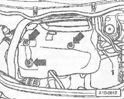
Remove the right front wheel. Remove soundproofing. Remove V-ribbed belt Remove hood. If present, unfasten the bracket. Remove engine cover -arrows-. Remove the sound insulation underneath.
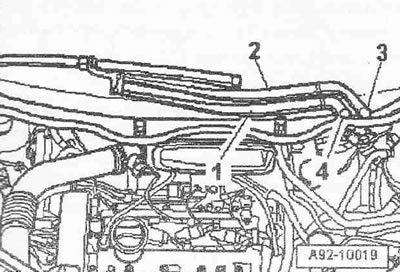
Pry off caps -3 and 4- on both parts of wiper arm with a screwdriver. Loosen the nuts on both parts of the wiper arm with a few turns. Loosen windshield wiper arms -1 and 2- on axles one by one with light wiggles. Completely unscrew the nuts and remove both parts of the wiper arm. If it is not possible to remove the lever in this way, then in this case it is necessary to use a standard puller.
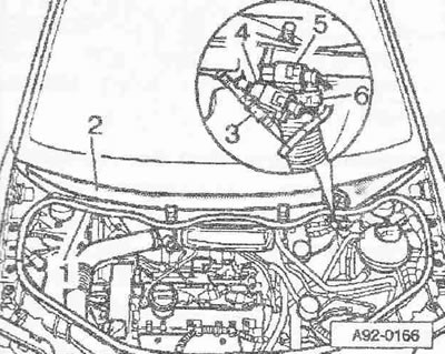
Disconnect washer fluid pipe -3-. If fitted, unplug electrical connectors -4 and 5- for heated windshield washer jets. Loosen hose clamp -6- using hose clamp pliers -VAG 1921- and remove drain hose from deflector grille. Remove rubber seal -1- from deflector grille. Remove air vent grille -2-. Unfasten washer fluid supply pipe.
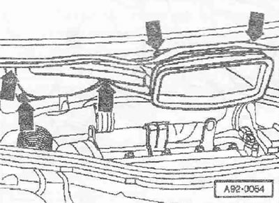
Remove nuts and bolts -arrows-. Pull the fresh air duct forward and remove it by turning it towards the right side of the vehicle.
Detach the air hose -1- from the suction pipe, to do this release the clips (where there are) -2- -arrow-.
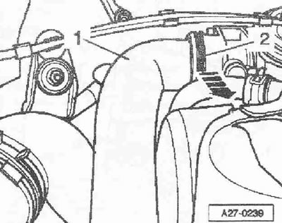
Vehicles with letter designation AMF, VNS
Remove resonator from air pipe -arrow-.
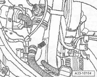
All cars
Unplug electrical connector -2- from air mass meter -G70-. Remove vacuum hose -1-. Loosen hose clamp -4- and remove air pipe together with air mass meter -G70-. Pos. -3- ignore.
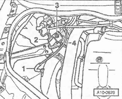
Unscrew tensioner for poly V-belt -arrows-.
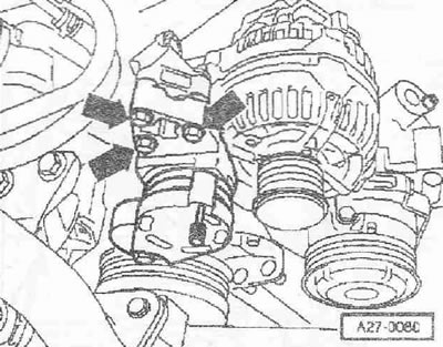
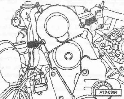
Remove top section of belt guard -arrows-.
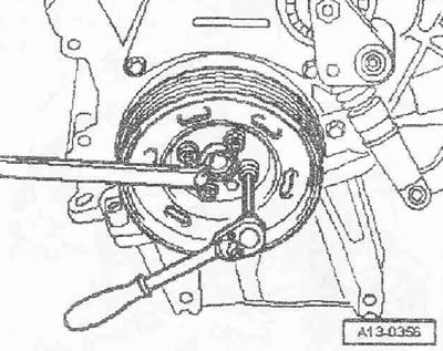
Unscrew the vibration damper, to do this, rest against the central bolt with a ring spanner.
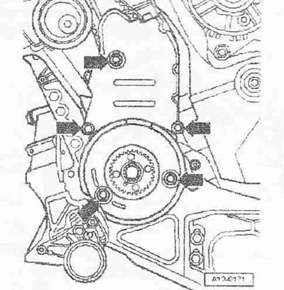
Unbolt center and bottom section of belt guard -arrows-.
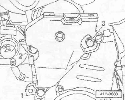
Remove lower bolt -1- for engine mount. Bolts -2 and 3- are loosened later.
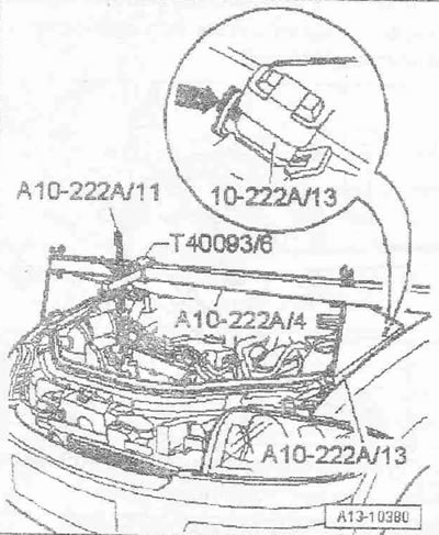
Position crosshead -10.222 A- with adapters -10.222 A/13- and adapter -T40093/6- on the edges of the wing bolts.
Carefully! In this case, insert adapter -10. 222 A/13- in the bonnet catches -arrow-.
Clamping screw in adapter -T40093/6- must be loosened. Install adapter -T40093/6- so that its bracket points upwards. Hook the hook of the lead screw carabiner -10.222 A/11- to the engine lug. Tighten the motor with the lead screw without lifting it.
Vehicles with cover for engine mounting
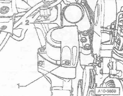
Remove the cover of the engine mounting, to do this unscrew the bolts -1 and 2-.
Loosen bolts -1 and 3- and remove bracket with engine mounting -2-.
Vehicles without engine mount cover
The nut -3- may only be loosened to replace the engine mount.
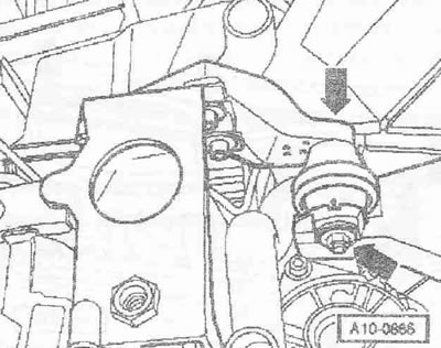
Remove bolts -1 and 2- and remove bracket with engine mount.
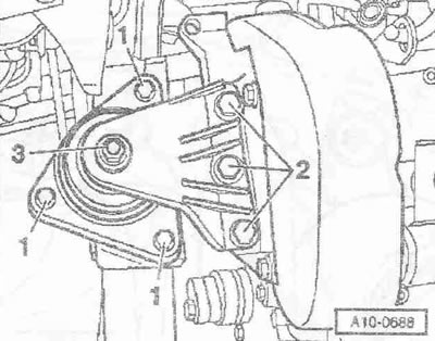
All cars
Remove upper bolts -2 and 3- and remove engine support. Pos. -1- ignore.
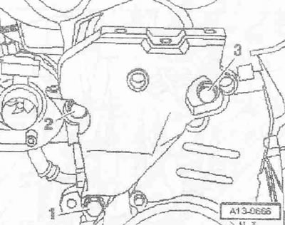
Carefully! It is allowed to scroll the engine only by the crankshaft in the direction of its rotation (clockwise). To rotate the engine shaft, install the center bolt on the crankshaft.
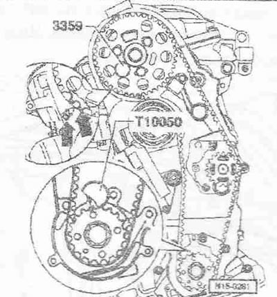
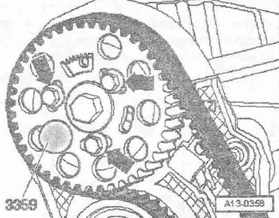
Set the crankshaft to the mark "TDC". The gap between the two teeth of the camshaft sprocket must be opposite the mark 37. on the rear of the belt guard -arrows-. Secure camshaft bushing with tool -3359-. Secure crankshaft sprocket with crankshaft stop -T10G50-.
Instruction. The crankshaft stop can only be pushed onto the sprocket teeth from the outside.
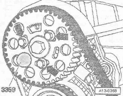
Markings for sprocket and crankshaft stop -T10050- must be opposite each other. The stud of the crankshaft stop -T10050- must engage in the seal bore. flange. Mark the direction of rotation of the toothed belt with chalk or felt-tip pen. Loosen bolts -arrows- of camshaft sprockets.
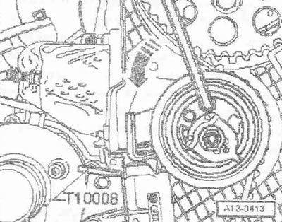
Insert the Allen key into the recess as far as it will go and turn the tensioning pulley anti-clockwise -arrow- until the toothed belt tensioner can no longer be secured with the locking plate -T10008-.
Instruction. To avoid damage, insert the Allen key as far as it will go. The toothed belt tensioner is oil damped and compresses slowly when a uniform force is applied.
Loosen the tension roller fixing nut.
Unscrew bolts -arrows- and remove toothed belt tensioner. Remove toothed belt.
Installation (valve timing adjustment)
The camshaft is secured with the lock -3359-. The crankshaft is secured with crankshaft stopper -T10050-. The tensioning roller is secured with locking plate -T10008-.
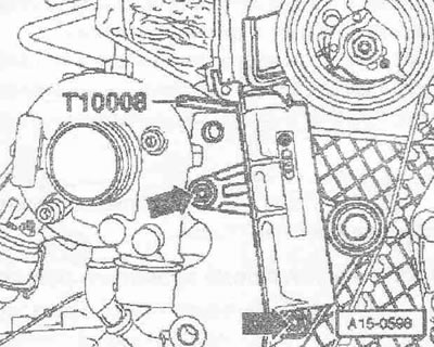
Instruction. Adjustment work on the toothed belt must only be carried out when the engine is cold. When turning the camshaft, none of the crankshaft pistons should be in "TDC". Risk of damage to valves/piston head.
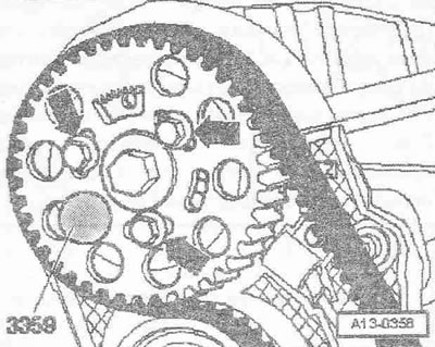
Screw in bolts -arrows- not completely. The camshaft sprocket should turn by hand, but not turn on its own. Turn the camshaft sprocket to the stop clockwise within its extended holes. Install the toothed belt on the camshaft sprocket, idler pulley, crankshaft sprocket and then on the coolant pump sprocket.
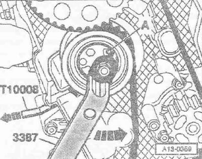
Install the belt tensioner. Set the position of the belt tensioner as follows: turn the eccentric counterclockwise with the pin spanner -3387- -arrow- until it stops -A-. Remove locking plate -T10008-.
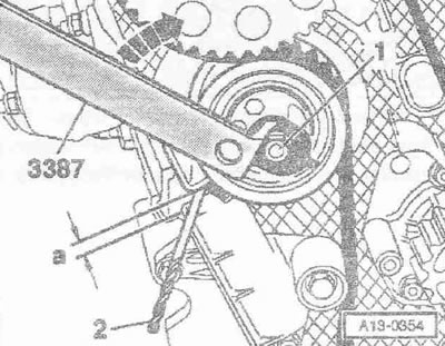
Tape the point and cutting edges of the 4.0 mm drill bit to avoid cuts. Slowly turn the tensioner clockwise -arrow- until the 4.0 mm drill shank -pos. 2- cannot easily pass between the tension arm and the tensioner housing. Gap -a- = 4.0±1.0 mm.
Instruction. The gap -a- decreases when the tensioning roller nut is tightened, so it must be set slightly larger. The gap -a- decreases when the engine is warm.
Lock the tensioning roller in this position and tighten the tensioning roller nut to a torque of 20 Nm + 45°. Tighten bolts -arrows- of camshaft sprocket first to 25 Nm. Remove retainer -3359- and crankshaft stop -T10050-.
Carefully! It is allowed to scroll the engine only by the crankshaft in the direction of its rotation (clockwise).
Turn the crankshaft 2 turns in the direction of rotation so that it is again in front of the mark "TDC".
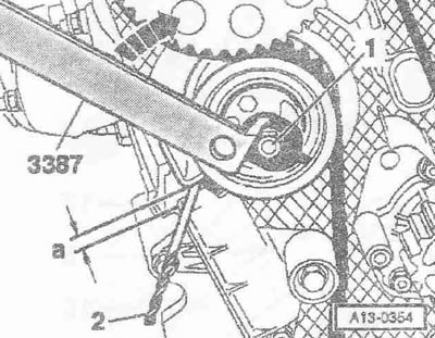
Re-check the clearance -a- between the tensioning lever and the tensioner housing. Gap -a- = 4.0±1.0 mm. If gap -a- does not correspond to specification, tighten tensioning roller as follows: hold tensioning roller with pin wrench -3387-, loosen nut -1- and turn tensioner until -arrow- reaches the specified gap -a -. Lock the tensioning roller in this position and tighten the tensioning roller nut to a torque of 20 Nm + 45°.
Checking the valve timing
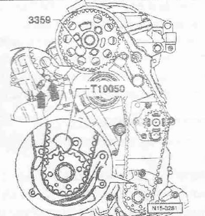
To check again, secure crankshaft sprocket with crankshaft stop -T10050-. Markings for sprocket and crankshaft stop -T10050- must be opposite each other. The stud of the crankshaft stop -T10050- must engage in the seal bore. flange. The pin of the crankshaft stop -T10050- must be inserted into the seal bore by turning. flange.
Instruction. If the crankshaft has crossed the mark "TDC", turn the crankshaft 1/4 turn back to re-align it in the direction of engine rotation to the mark "TDC". The shaft must not be turned in the opposite direction of engine rotation to correct the setting of the crankshaft stop -T10050-. Check that the camshaft bushing -3359- can be secured using the locking pin.
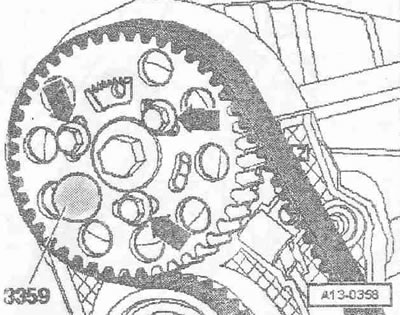
If bushing can be locked: Loosen bolts -arrows- of camshaft sprocket. Fit a spanner wrench onto the camshaft center bolt. Rotate sleeve until locking pin -3359- can be inserted. Tighten the bolts -arrows- of the camshaft sprockets finally with a torque of 20 Nm + 45° (1/8 turn). Remove the retainer and crankshaft stopper.
Carefully! It is allowed to scroll the engine only by the crankshaft in the direction of its rotation (clockwise).
Turn the crankshaft 2 turns in the direction of rotation so that it is again in front of the mark "TDC". Repeat the valve timing check.
Installation
Further installation is carried out in the reverse order, while observing the following: The hoses and the hose fitting of the charge air system must be free of oil and grease before installation. Never use lubricants. Install the engine mount. Install the lower center part of the belt guard. Install vibration damper. Install bracket with engine mount. Install the upper part of the belt guard. Install the air ducts in the clamps. Install poly V-belt. Install the wiper arm.
Tightening torques:
- Toothed belt tensioner to cylinder block; 15 Nm
- Camshaft sprocket to bushing: 25 Nm
- Tension roller to cylinder head: 20 Nm + 45°
- Lower part of the belt guard to the cylinder block: 10 Nm 1)
- Center section of belt guard to cylinder block: 10 Nm 1)
- Engine support to cylinder head: 45 Nm
- V-ribbed belt tensioner to accessory bracket: 22 Nm
- Engine compartment cover to bracket: 22 Nm
1) Use thread varnish to tighten bolts.

Visitor comments