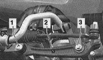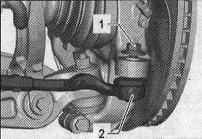
Unscrew the nut -1- of the tie rod end -2- until it is flush with the thread of the pin. When loosening, if necessary, keep it from turning.

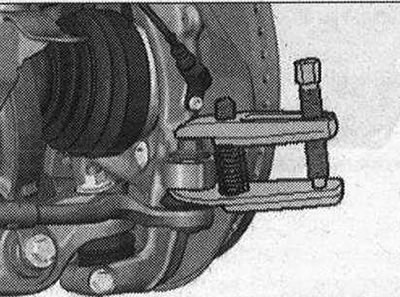
To protect the thread, leave the nut on the pin screwed in a few turns. Press the tie rod end out of the wheel bearing housing using a ball joint puller -T40010 A-. Then unscrew the nut.

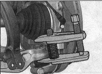
Make sure that both arms of the puller lever are parallel to each other at the moment of maximum force application; correct the position if necessary. Disconnect bolted connection 1.

To remove bolt -1-, depending on the vehicle side, turn the steering gear all the way to the left or right. Remove the support arm from the mount and move it back. Loosen the ball joint pin nut until it is flush with the ball joint pin threads. When loosening, if necessary, keep it from turning. Using a ball joint extractor -T40010 A-, press the suspension pin out of the conical seat. Make sure that both arms of the puller lever are parallel to each other at the moment of maximum force application; correct the position if necessary. Do not damage the joint boot! In order not to damage the hinges of the upper suspension arms, it is necessary, for example, using a lift for the engine and gearbox - VAG 1383 A-, to provide support for the hub bearing housing against the reverse movement of the shock absorbers. Unscrew the nut from the suspension arm hinge pin. Remove the support arm.
Installation
Install in reverse order. In this case, tightening torques must be taken into account. Say-tape blocks have a limited working range of twisting. Therefore, wheel suspension bolts should only be tightened when the vehicle is in the no-load or standard suspension position. Raise the wheel support with the suspension in static position on vehicles with coil springs. When tightening the screw connection -1-, the support arm must be pressed against the inside of the vehicle. Remove any remaining adhesive from the ball joint pin threads. For vehicles with automatic transmission and headlight range control, perform the basic installation of the headlights. After removing and installing the vehicle level sensor or loosening the linkages on vehicles with electronic damping control, the standard suspension position must be re-adjusted. After recalibrating the adjustment position on vehicles with lane assist, the lane departure warning control unit -J759- must be recalibrated. Tighten the wheel. It is necessary to adjust the wheel alignment angles.

Visitor comments