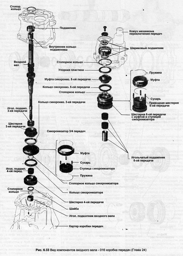
2. Raise the 4th needle bearing gear. If the bearing needs to be removed from the gear, paint the location of the bearing in the gear.
3. Remove the 4th gear synchronizer ring.
4. Remove the retaining ring securing the synchronizer hub, remove the hub from the shaft.
5. Remove the 3rd gear synchronizer ring, 3rd gear and needle bearing.
6. Mark the gear and bearing so that the bearing is not upside down during assembly.
7. Before assembly, check that all parts are clean.
8. Lubricate the needle bearing of the 3rd gear with gear oil, install it on the shaft.
9. Install the 3rd gear.
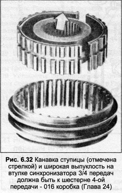
10. If the synchronizer has been disassembled, assemble it so that the hub is installed according to the marks. Later models do not have marks, but are assembled with a hub groove and a wide part of the sleeve to the 4th gear.
11. Install three locking cotters into the hub before installing the bushing, then secure the cotters with circlips. The location of the circlips is shown in Fig. 6.4, the sharp end of the spring is inserted into the blocking nut.
12. Install the 3rd gear synchronizer ring on the pinion cone, measure the gap shown in Fig. 6.5. This gap must not exceed the value given in Specifications, otherwise install a new synchronizer ring.
13. Note that the slots in the synchronizer hub bore are grooved at one end. With this end, put the hub on the shaft. Put on the 3rd gear. Its hub also has a groove at one end (Pic. 6.32), this side must face the 4th gear.

14. Slide the synchronizer onto the input shaft by first turning the 3rd gear synchronizer ring so that the grooves on it line up with the synchronizer lock nuts.
15. Insert the retaining ring onto the synchronizer hub, then push the synchronizer back away from the retaining ring. This will increase the gap between the synchronizer and the 3rd gear which provides better lubrication to the 3rd gear bearing.
16. Install the 4th gear synchronizer ring, aligning the grooves in it with the synchronizer lock crackers, check the clearance as described in paragraph 12.
17. Install the 4th gear and bearing, lubricating them first with gear oil, install the thrust washer and finally the circlip.
18. Measure the axial clearance between the 4th gear and the thrust washer. This gap should be 0.20-0.35mm, smaller gap is even better. Retaining rings are available in different thicknesses to obtain the required clearance, namely 1.65, 1.70 and 1.75 mm. Note that on later transmissions the shaft has been changed and the thrust washer is not installed. Instead, a single thicker retaining ring is used, the axial clearance is no longer adjustable.


Visitor comments